

3 min read
Tolerance stack-up can be a unique challenge when forming and machining a series of parts for a complex product. The design may focus on functional requirements and aesthetics but once you move to manufacturing, the tolerance between features becomes extremely important. You have to ensure everything fits together, with no gaps or misaligned pieces that exceed your allowable tolerances and result in a poor quality product.
 Individual measurements and manual calculations of each feature are possible but you want to see the tolerance stack from a holistic view. A 3D scan enables you to dial in the machining process and design custom fixtures for precision cutting, which maintains the required tolerance of each feature on every part.
Why Use 3D Scanning to Evaluate Precision Part’s Tolerance Stack-Up
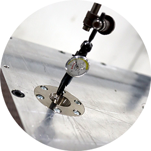
When putting multiple parts together, you need a high level of precision when machining the features to have them line up across one another. If you’re not using 3D scanning technology, the likelihood of exceeding the allowable tolerance increases exponentially. Parts with odd shapes, curves, or recesses are harder to measure and dial in precisely when using standard techniques like a caliper to track individual dimensions.
 3D scanning the part enables you to extract precise measurements of each feature and quickly calculate the tolerance stack-up across all the workpieces. You can dial in the CNC machine to ensure each feature stays within the allowable range and maintain the accuracy with a custom fixture design even when working with oddly shaped parts.
Managing the Tolerance Stack-Up for Molded Surfaces vs Machined Features
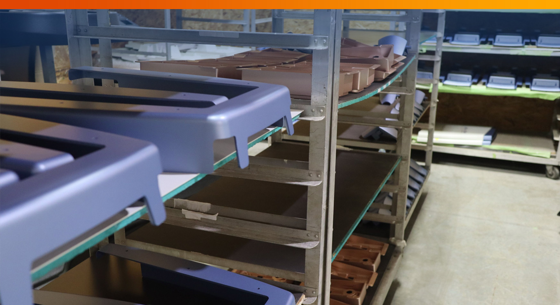
In molded parts, the material only touches one part of the mold. Because the mold doesn’t change, you can maintain the repeatability and precision of each piece. Designing the mold strategically for the thermoforming process allows you to manage the tolerance on the cosmetic side of the part with a high level of accuracy.
For the attachment features, you have to set up the machining process for each part which could introduce greater variance between parts. To achieve the required precision for the assembled product, you’ll need to optimize the secondary machining of the fastening features on the backside of the part.
To verify that each attachment feature falls within the allowable tolerance and every piece fits together as per the initial design, a 3D scan will show you how accurately your machining and fixturing processes are set up.

Why Kenson Plastics Use 3D Scanning to Manage Tolerance Stack-Up Precisely
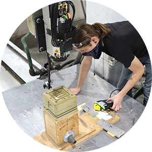
 Kenson Plastics controls machining variance using our 3D scanning technology to dial in the CNC programming and set up. When you need your part features to fit precisely, there is no better way to validate and verify the tolerance stack-up than creating a 3D scan of each part and modeling the pieces in a CAD system. Ideally, you’ll want to form as many of the features as possible using a thermoforming process but we understand this isn’t always possible.
For situations where you have to ensure the accuracy of secondary machined features, only a 3D scan will allow you to zone in on each element and determine what is causing you to be Out of Tolerance (OoT). With custom fixturing designs to hold the part in place during the machining process, you can eliminate variance and ensure higher precision during manufacturing.
Kenson uses 3D scanning, strategic mold design, and custom fixturing to manage the tolerance stack-up precisely for the entire manufacturing process.
To see our advanced manufacturing and thermoforming solutions in action, book a virtual tour from Kenson Plastics here.

Related Posts
How Thermoforming and Plastics Have Transformed Healthcare
Modern medical devices often exhibit the latest and greatest of our cutting-edge technological...
Inside Kenson Plastics: Precision Thermoforming Built for What’s Next
Industrial Designers, Check Out These 6 Tips to Creating a Sexier, High-End Product
Designing durable, high-end, niche products at low volume using a cost-effective manufacturing...